Article

Performance Assessment of a Three-Dimensional Printed Porous Media Produced by Selective Laser Melting Technology for the Optimization of Loop Heat Pipe Wicks

1
NAITEC Centro tecnológico en automoción y mecatrónica, Tajonar 20, 31006 Pamplona, Spain
2
Departamento de Ingeniería nuclear y mecánica de fluidos, Escuela Superior de Ingeniería de Bilbao, Universidad del País Vasco/E.H.U., Plaza Ingeniero Torres Quevedo, 1 (edificio 1), 48013 Bilbao, Spain
3
Departamento de Ingeniería estructural y mecánica, Escuela Técnica Superior de Ingenieros Industriales y de Telecomunicación, Universidad de Cantabria, Avenida de los Castros s/n, 39005 Santander, Spain
*
Author to whom correspondence should be addressed.
Appl. Sci. 2019, 9(14), 2905; https://doi.org/10.3390/app9142905
Submission received: 16 June 2019 / Revised: 17 July 2019 / Accepted: 18 July 2019 / Published: 19 July 2019
(This article belongs to the Section Optics and Lasers)

Abstract

:

Featured Application

Thermal superconductors for cooling electronic devices.

Abstract

The primary wick in a loop heat pipe device is a key component that is central to the operation of the device. Both high permeability and capillary pumping capacity, two properties highly dependent on wick structure, are strongly desirable for a satisfactory thermal performance. In this paper, selective laser melting (SLM), a three-dimensional (3D) printing technology, is used to create a primary wick for an 80 W heat transfer application. The permeability and capillarity values of this wick, experimentally measured, are compared with those built with the most widely used technologies nowadays, such as powder sintering and meshes. In this study, the SLM scaffold is shown to satisfy the minimum values required by the application in terms of capillarity and permeability: 0.031 mm/s and 4 × 10⁻¹² m2, respectively. Our comparative study revealed that the wick produced with the SLM technology presented higher values of permeability, by two orders of magnitude, and slightly higher capillary figures than those corresponding to powder sintering for such application. However, it had capillary values well below those of a stainless-steel mesh. The hydraulic behavior of the SLM wick was better than that of the sintered copper powder, because it not only met the above-mentioned specifications, but it also improved its performance.

Graphical Abstract

1. Introduction

Loop heat pipes (LHP) are widely used for thermal management and cooling in electronics [1,2,3] because of their high capacity to transmit heat over long distances with only small drops in temperature. The primary wick [4] is central to these devices, because it provides the necessary capillary force to pump the working fluid around the device from the heat source to the heat sink [5,6,7].
Porous wicks for LHP are mainly manufactured by powder sintering technology [8,9,10], which is a very well-known technology. Nevertheless, two other techniques are also used for LHP: meshes and foams. With the advent of three-dimensional (3D) printing, the production industry may be on the eve of a manufacturing revolution. The potential of wick manufacturing by 3D printing to improve LHP performance has already been experimentally assessed [11,12,13].
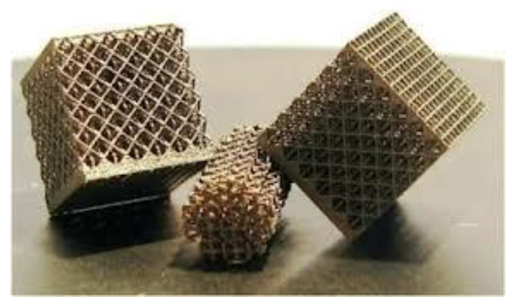
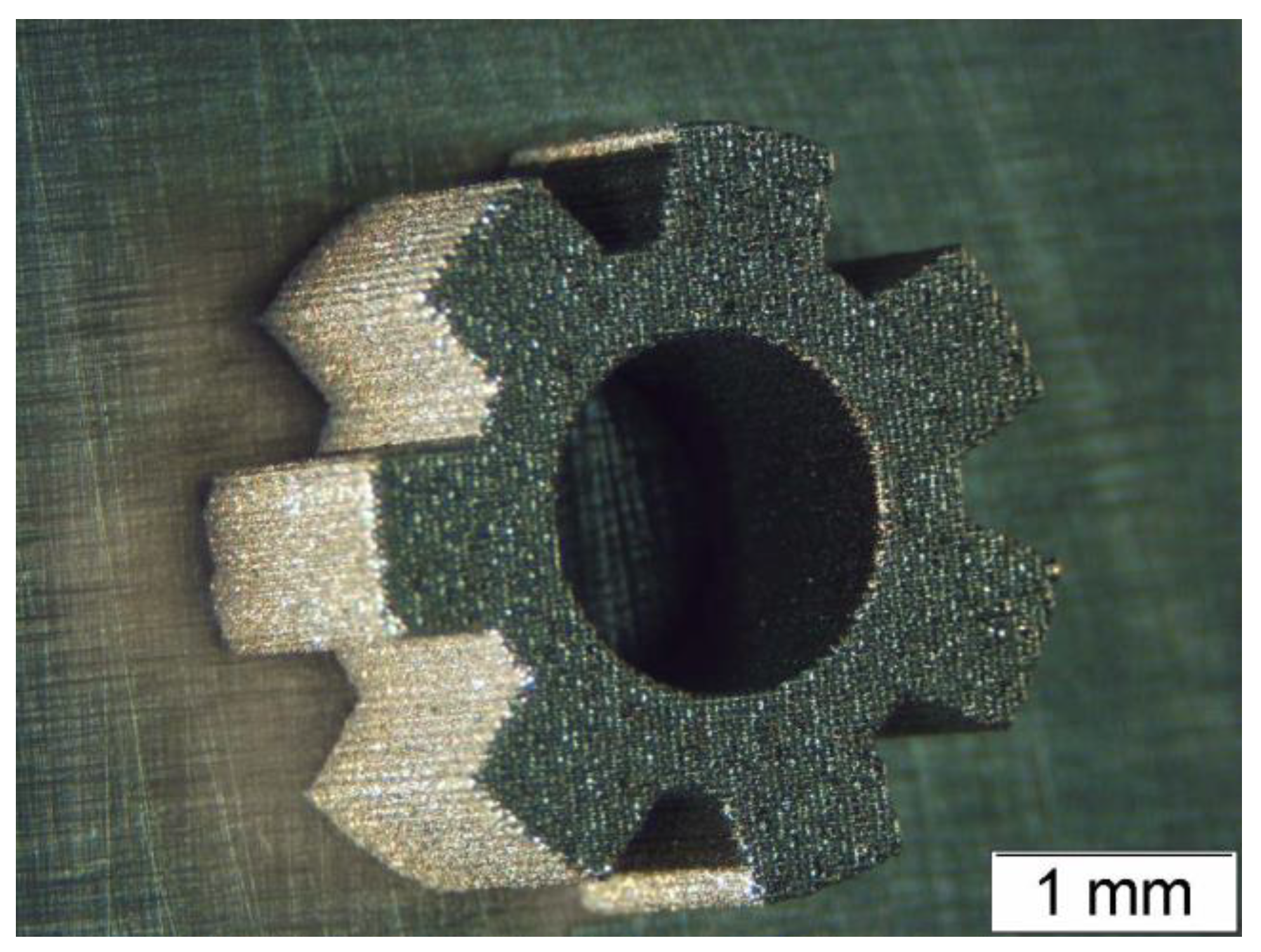
Selective laser melting (SLM) is a technology for the rapid manufacture of complex geometries (Figure 1), which would not otherwise be possible. It also controls the specific pore size, distribution, and connection.
The type of material, its porosity, internal structure, geometry, and wettability are among the key determinants of the porous media performance [14,15,16]. Precisely how such parameters affect the capillary action and the permeability of the medium is essential to the design of an LHP device, (both high permeability and high capillary actions are required) [17]. Aiming at performance optimization, these two effects need different pore sizes: small for capillary action and pumping, and larger for permeability [18,19].
The capillary pumping should be sufficient to ensure the correct supply of fluid to the LHP evaporation zone, preventing any dry spots from appearing at the wick’s liquid-vapor interface, which means that liquid velocity through the wick ( m ˙ ) must be larger than the liquid evaporation rate at the liquid-vapor interface ( m ˙ C ) [20].
m ˙ m ˙ C
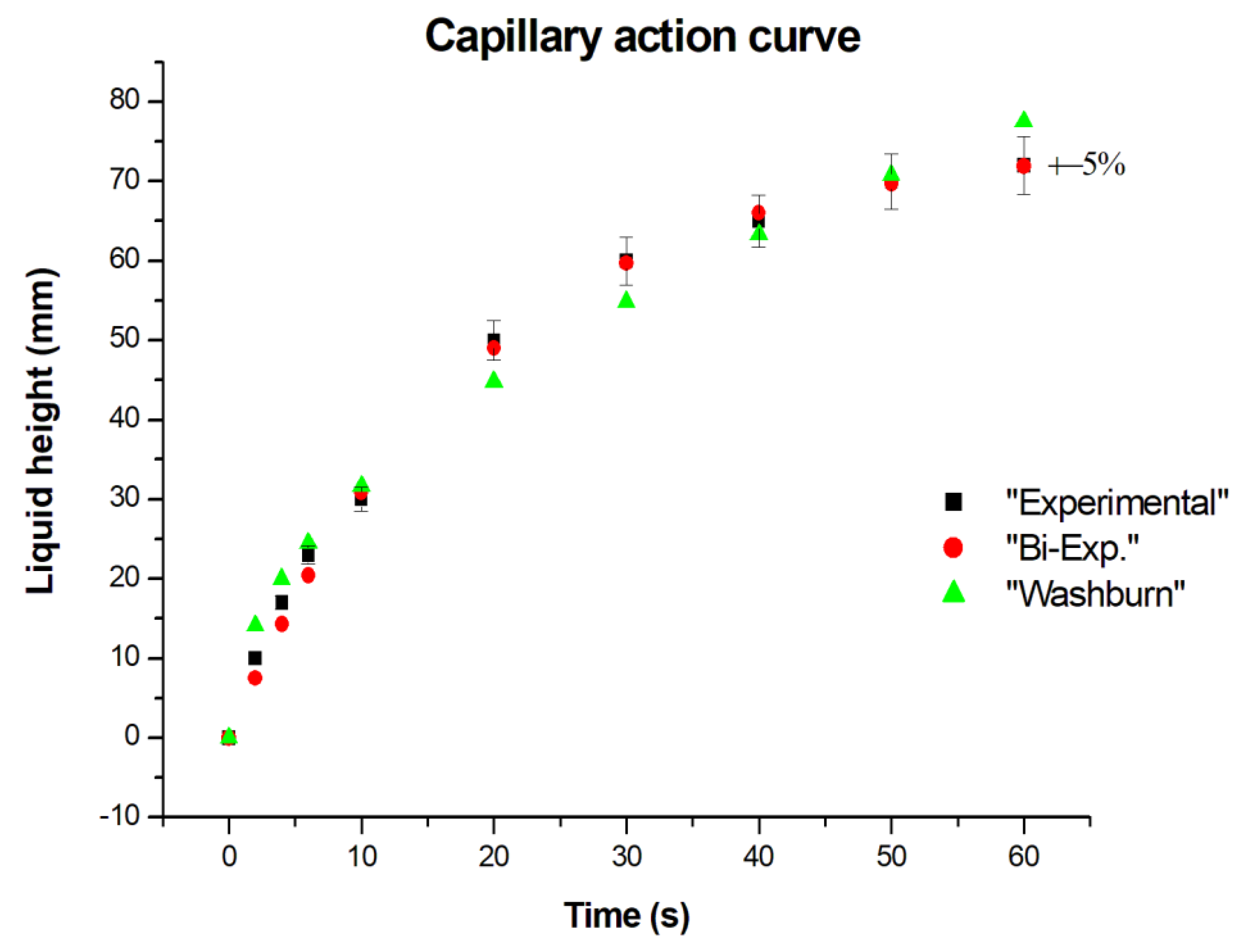
It is known that the Washburn equation determines the capacity of capillary pumping or pumping height (y) of a bundle of parallel cylindrical tubes as a function of time (t) and some fluid properties (surface tension (σ), contact angle (ϕ), viscosity (µ)), and the tube radius (reff).
y 2 = r e f f · σ · cos ϕ 2 μ t
Its use, although with reservations, has also been extended to the imbibitions into a porous medium. These reservations are: uniform pore distribution, constant pore size, and gravitational forces negligible compared with the capillaries, but these conditions rarely occur in real cases. In Section 3.1, an error analysis was performed between the predictions of the Washburn equation and the experimental [21] values in order to confirm the law’s adequacy. In this article, the Washburn equation is not considered since the biexponential expression best fits the experimental data. Working fluid wettability is another influencing parameter already studied in many works [22].
For an 80 W loop heat pipe application with a primary wick of 30 mm in height, the fluid flow rate at the top of the wick (liquid-vapor interface) must be higher than or equal to 0.031 mm/s.
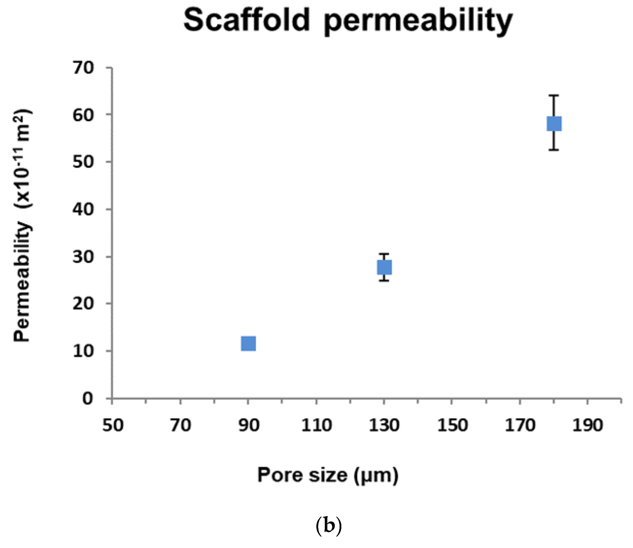
The permeability of the wick, therefore, depends greatly on its internal structure (pore size and pore connection). Theoretical permeability as a function of the internal structure of the porous medium has been widely studied [23]; however, these permeability-internal structure relations are valid for specific internal arrangements [
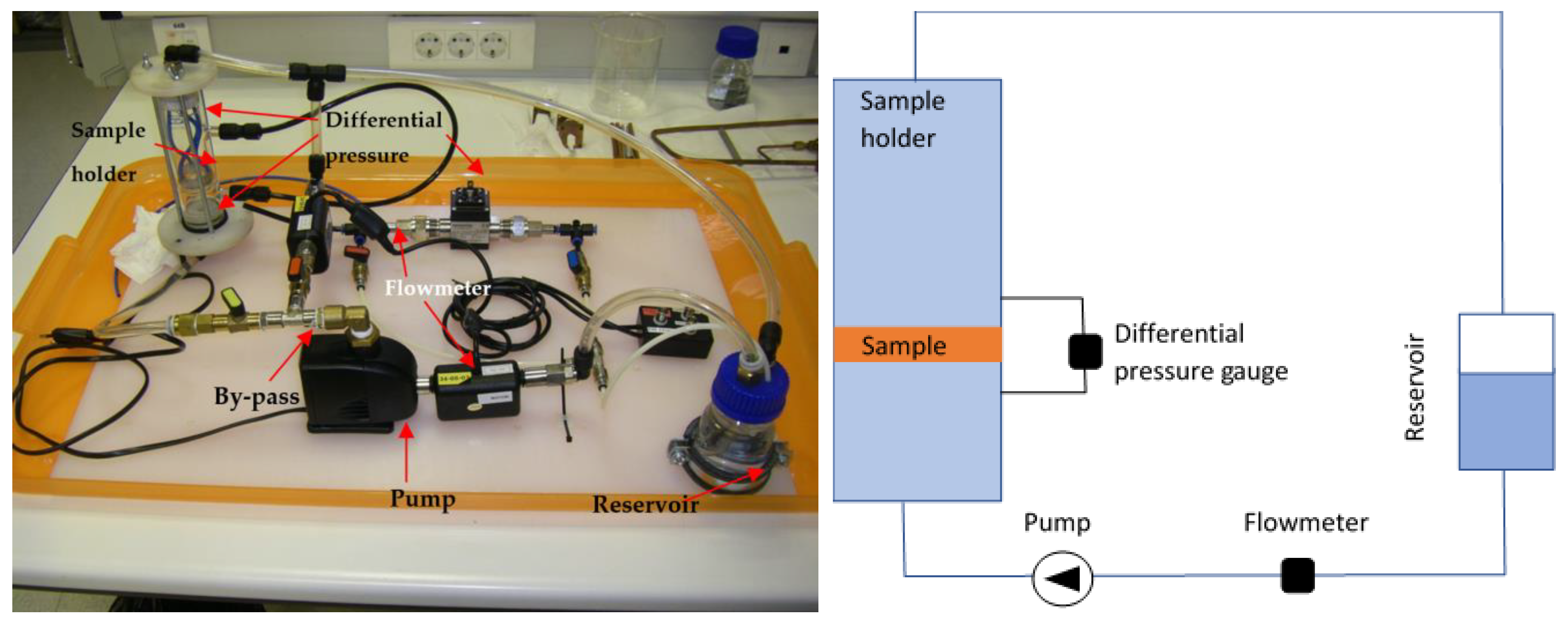
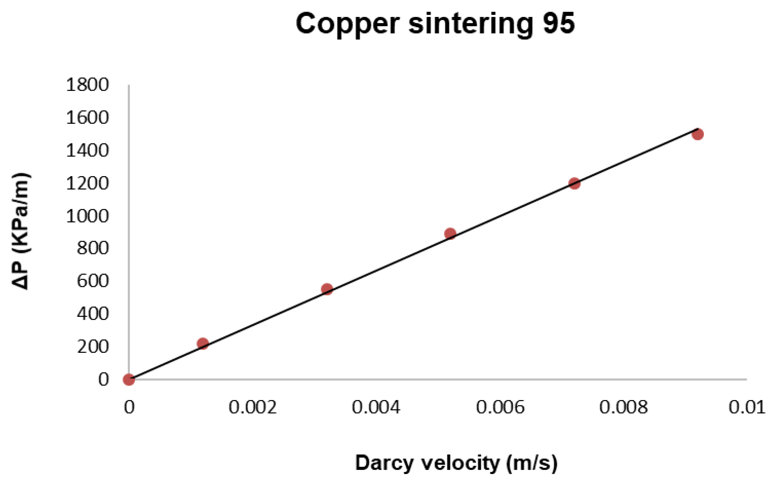
24] that are not always present in nature. Darcy’s law is a simple proportional relationship between the instantaneous flow rate through a porous medium of permeability (κ), the dynamic viscosity of the fluid, and the pressure drop over a given distance in a homogeneously permeable medium. In this work, it is used to obtain the permeability of different porous media working with the same fluid (methanol) by measuring pressure drop and flow rate through them. In the above-mentioned application, the pressure drop in the wick must be less than or equal to 100 Pa to arrive at the proper flow rate into the LHP [22]. The wick permeability must, therefore, be greater than 4 × 10⁻¹² m2.

2. Aims and Methodology

The main objective of this research is to experimentally determine the capillary action and permeability of a SLM wick for a loop heat pipe [25,26,27] and to compare both results with those of other similar wicks made of conventional manufacturing techniques (sintering, mesh, etc.) in order to evaluate the wick performance.
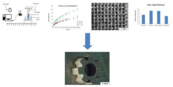
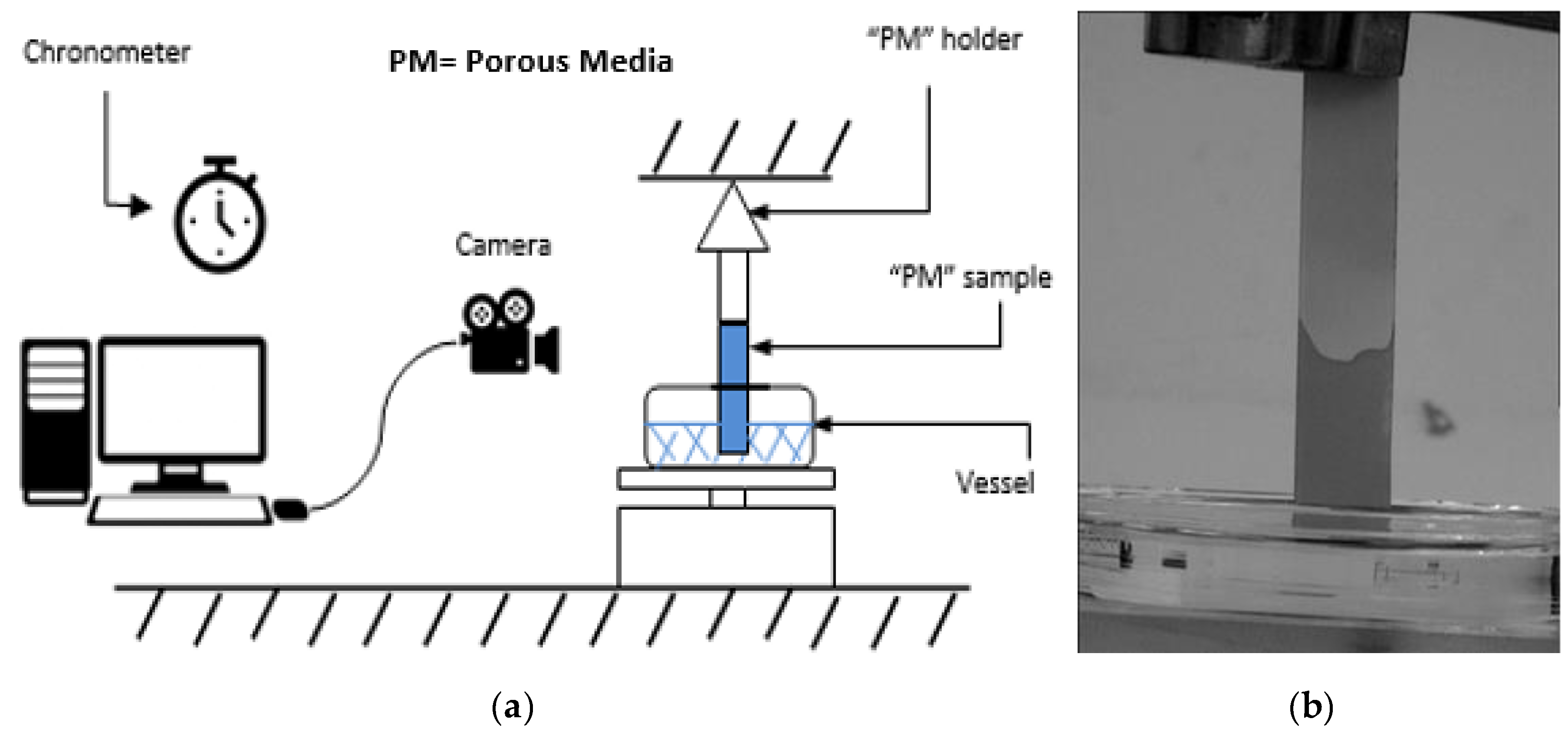
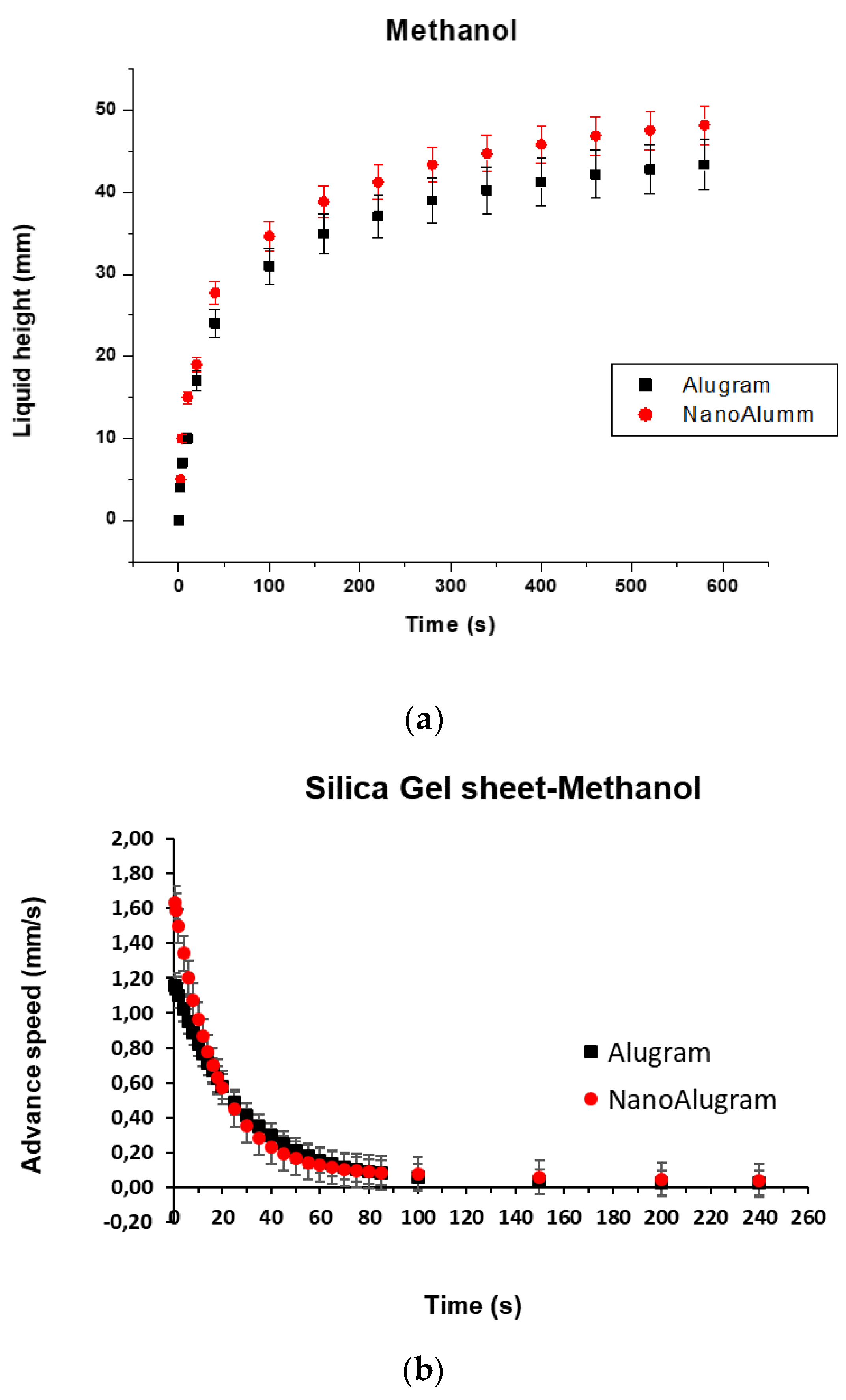
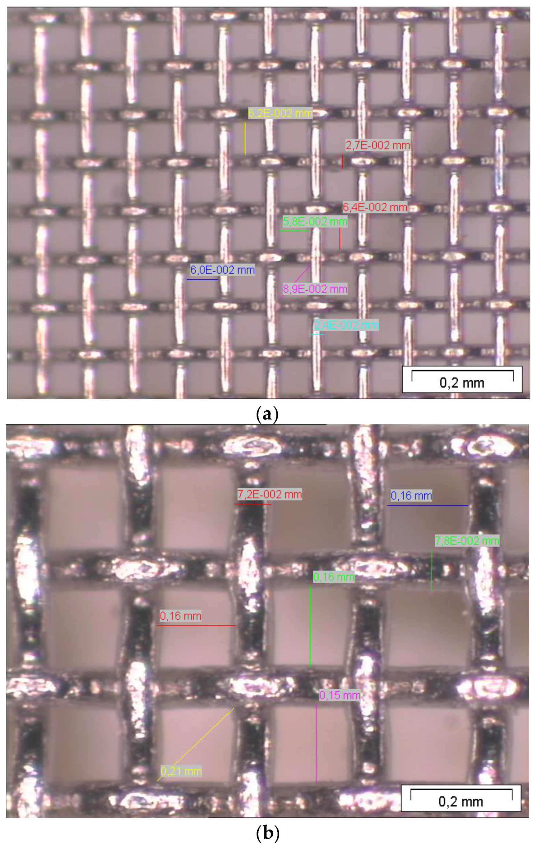
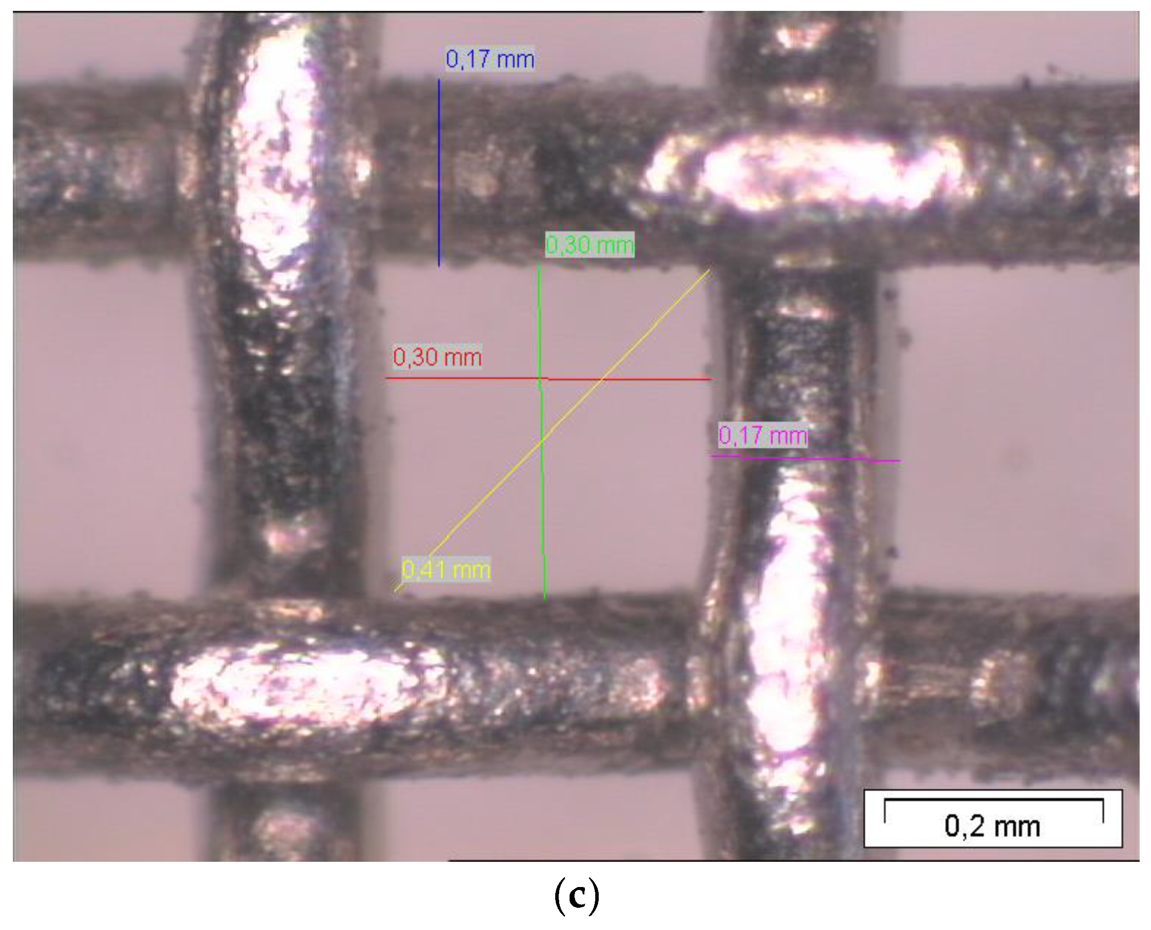
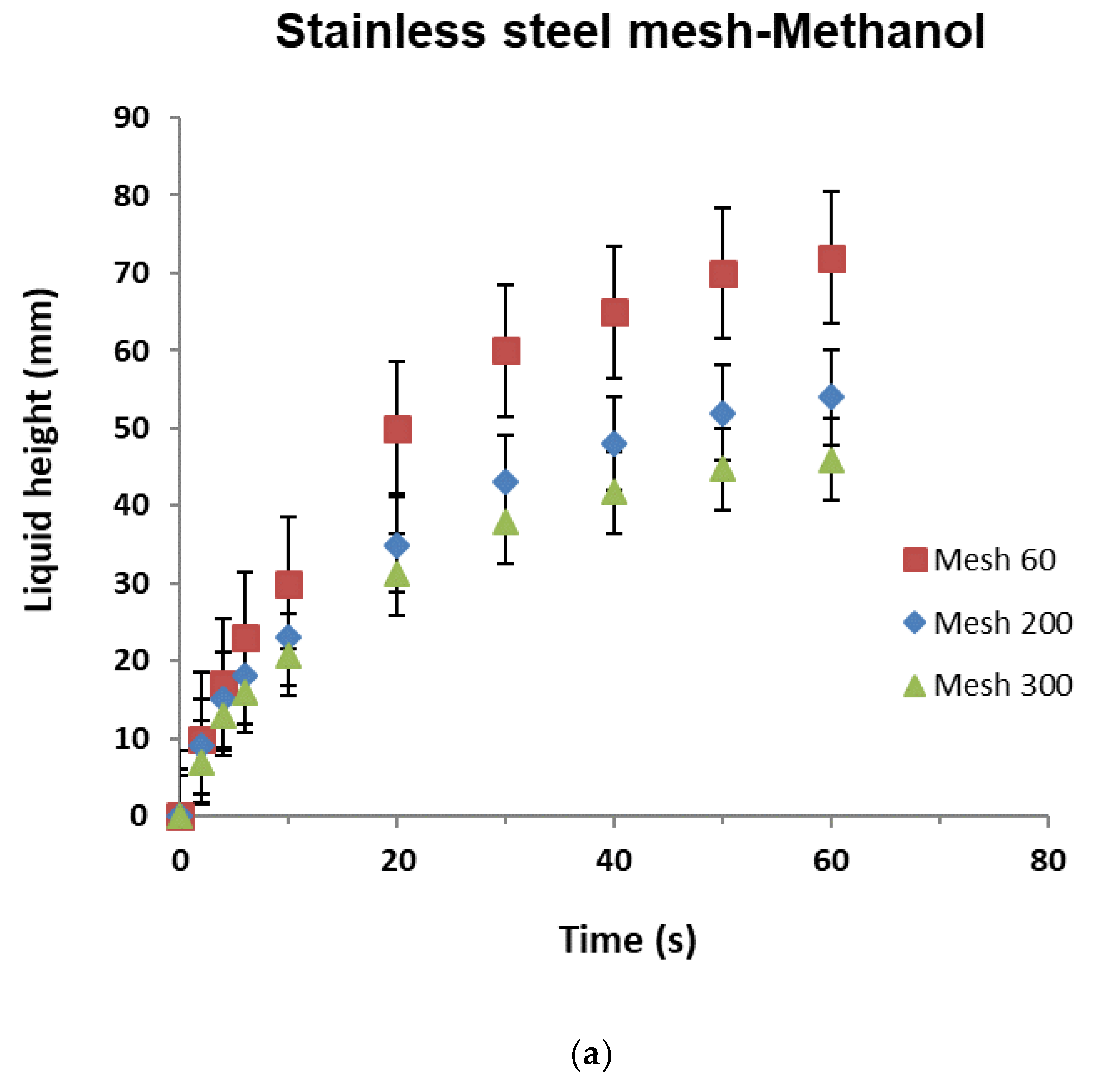
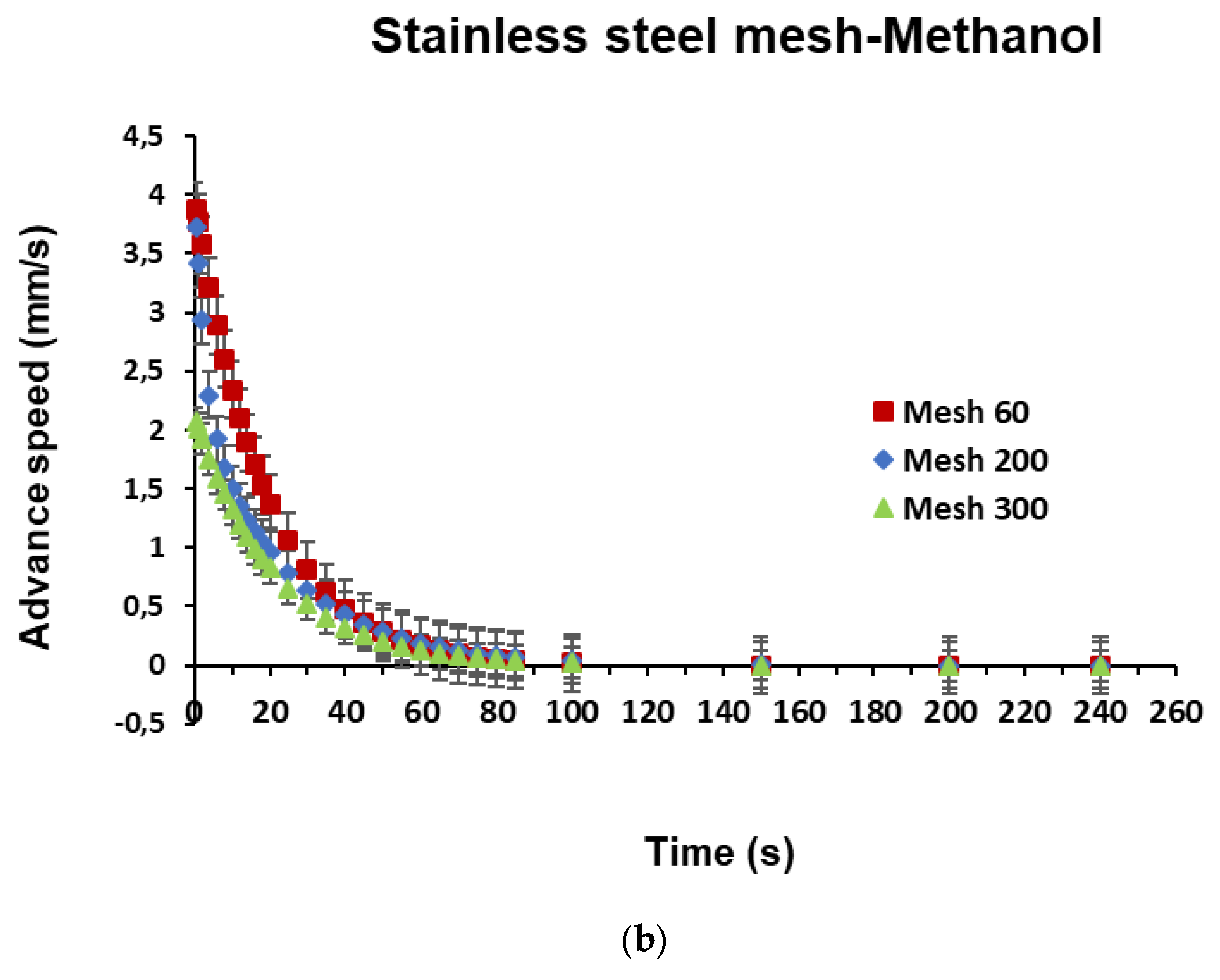
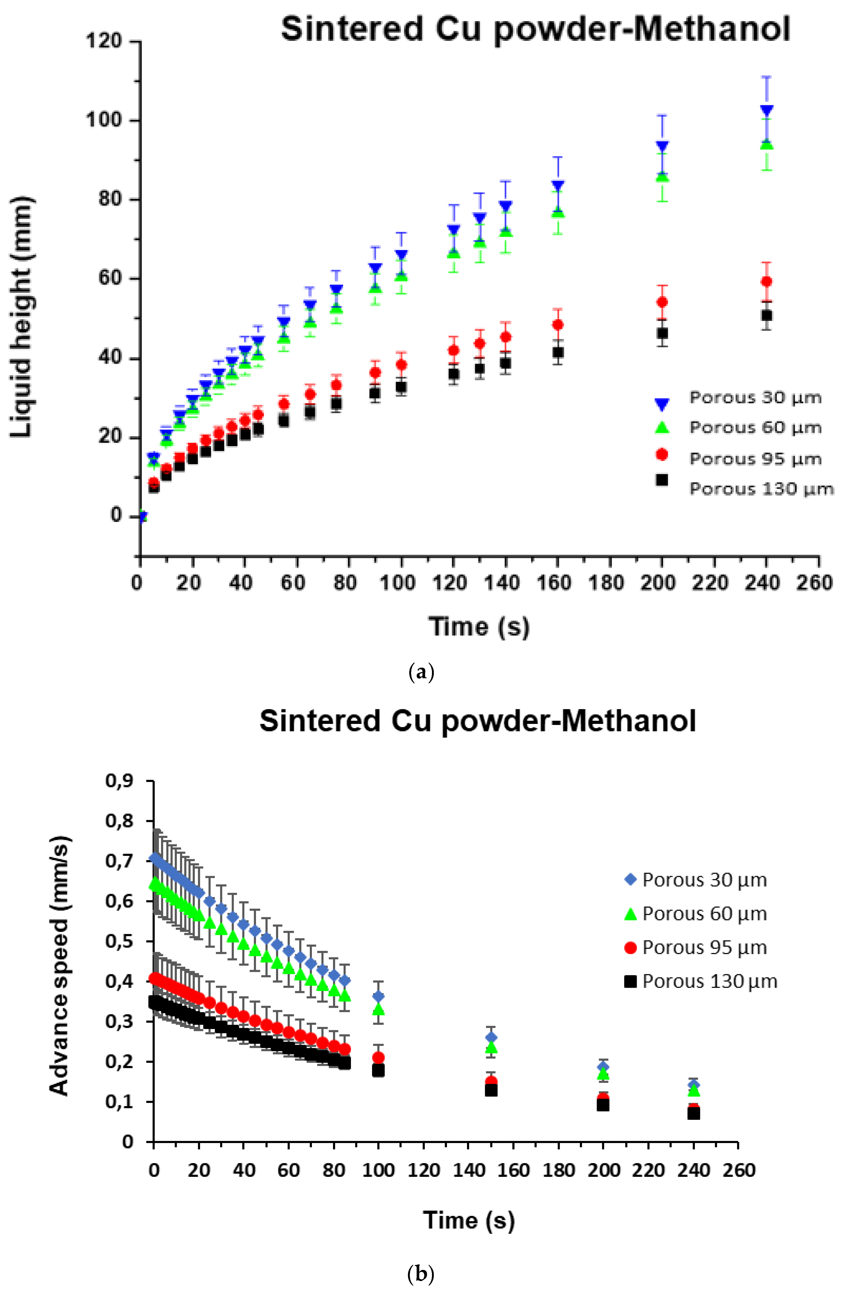
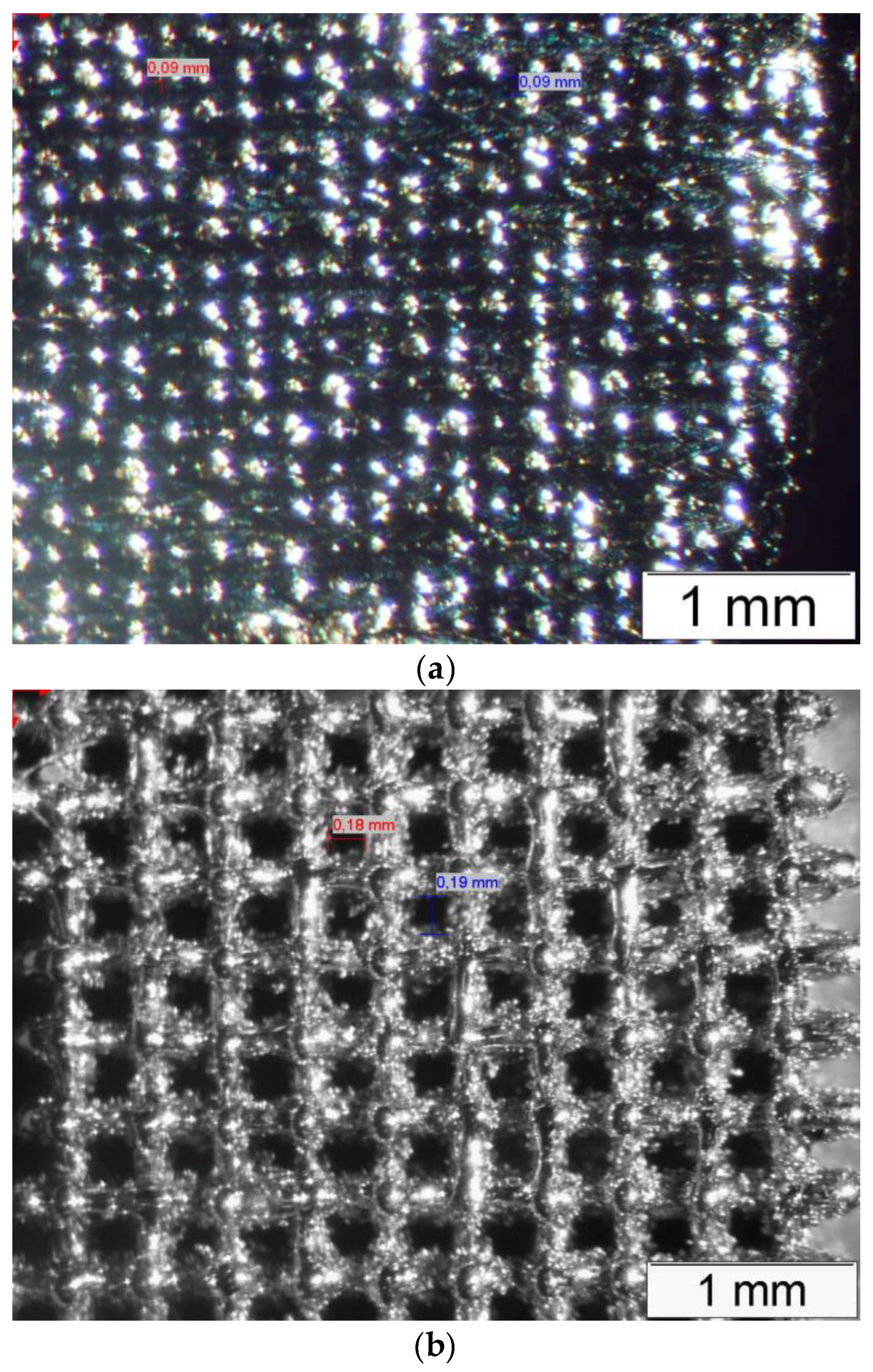
Experimentation is presented as an efficient means of obtaining the flow velocity through a porous media, the capillary action curve, which will be obtained by measuring liquid height versus time for several materials and techniques: (i) sintering, (ii) meshing, and (iii) SLM. The experimental method is also the most accurate way of determining the permeability of a medium as porous as an LHP wick with a complex internal structure. In this case, samples with different pore sizes (D) were built through two different technologies, sintering and SLM, and were finally tested.
The working liquid used throughout all the experiments was methanol, the thermophysical parameters of which are: density ρ = 786.47 (kg/m3), enthalpy of vaporization hfv = 1,169.2 (kJ/kg), surface tension σlv = 22.16 (N/m), and viscosity µ = 544.61 (µPas).

3. Measurement Procedure

3.1. Capillary Action

Figure 2a shows the scheme of the test bench used for the capillary action measurement of different porous media (PM), together with the detail of the real picture of a sample silica gel (Figure 2b), in which the liquid (methanol) height can be clearly appreciated.
It consists of:
  • A vessel to deposit the liquid;
  • A wick sample clamping arm;
  • A chronometer;
  • A camera;
  • A PC-data logger. PC: personal computer
The vessel was filled up with methanol and a sample wick was set up at one end in the clamping arm to which the camera was also attached (see Table 1, showing the main equipment).
Then, the holding arm with the wick sample was placed upright next to the vessel, submerging the other wick ends into the liquid contained in the vessel. The liquid immediately began to rise up through the wick, so the ascent of liquid was recorded [28]. The heights recorded in this way were plotted to obtain the wick capillary action curve (Figure 3). Each data point is the average result of 4 tests.
The first step was to evaluate the suitability of the Washburn equation for determining the capillary curve. This evaluation was made by estimating whether the predicted values (Washburn) were within the ±5% error of the experimental values. Considering the stainless-steel mesh of 60 μm, it was observed (Figure 3) that most of the Washburn values were outside the ±5% threshold.
Therefore, a bi-exponential adjustment of the experimental data was done to obtain the analytical form of the liquid height, in a similar way to [29], with a view to the performance of further comparative capillary tests. This adjustment predicted values within the ±5% threshold.
y   =   A 1 [ 1 e ( t   t 1 ) ] + A 2 [ 1 e ( t t 2 ) ]
Deriving Equation (3) with respect to time yields the speed of advance of the liquid (4) [30]:
α = A 1 t 1 e ( t t 1 ) + A 2 t 2 e ( t t 2 )
where y represents the liquid height, α the advance speed, and A1, t1, A2, and t2 are constants of the fluid and wick combination that were experimentally obtained. As the liquid ascended, the speed dropped to the point where it reached zero (maximum height reached = A1 + A2).
Two clearly differentiated regimes were observed on the curve; a first one in which the height varied very rapidly (initial regime) and a second one in which the variation of height was slightly slower (inertial regime). Regarding the advance speed, the maximum value corresponds to α m a x = A 1 t 1 + A 2 t 2 . Constant t1 represents the time at which the height reached is 67% of the maximum height and t2 is the time at which the speed of advance is decreased to 37 % of maximum speed.

3.2. Permeability

Permeability (κ) is defined as the rate of fluid circulation through a porous medium. The complexity of the internal configuration of the porous medium means that there is no general relationship that determines the value of κ as a function of the effective porosity τ (tortuosity), defined in terms of the path, from the entrance to the outlet, that the fluid has to travel through the medium and pore size, etc. [31]. Despite this complexity, some approaches aim to simplify this internal structure [32] so as to obtain an expression for permeability by solving the Navier–Stokes (N–S) equations at pore level [33,34].
Hence, the use of permeability measurement devices [35,36,37,38,39] permits indirect determination of wick permeability by measuring the pressure loss (ΔP) and flow rate through the medium. The flow at pore scale must be in the Darcy’s regime, which means that the Reynolds number (Re) must be Re < 10 [40].
In this section, we intend to determine the effect of pore size (D) on the permeability of the medium on an experimental basis. A JEOL (JSM5900LV, ELIONIX, Tokyo, Japan) scanning electron microscope (SEM) was firstly used to determine the pore size, while the porosity level was determined by directly measuring sample volumes and weights on our permeability test bench. The main features of the SEM are shown in Table 2.
On the permeability test bench, methanol flow tests were performed at low speeds (0–0.0012 m/s), as shown in Figure 4, in order to characterize the Darcy’s curve from which the permeability (slope) could be obtained.
Permeability quantifies the degree of fluid movement within a solid material. A specific fluid flows through a closed circuit with the following main elements: a pump, a flow-meter, a reservoir, a sample holder, a by-pass, and a differential pressure gauge, as depicted in detail in Figure 4 (left). A simplified scheme is shown on the right side of this figure.
The pump circulates the fluid inside the closed circuit, discharging it into the reservoir. The reservoir presents a liquid-free zone preventing vapor flow inside the circuit, which would otherwise distort the results. The sample holder, where the sample is placed for measurement, has two pressure measurement points situated immediately before and after the sample. These points, to which the manometer is connected, determine the pressure loss in the sample. A flow-meter measures the amount of circulating fluid inside the circuit. Finally, a by-pass around the sample holder is inserted for fine-tuning of flow control throughout the whole sample.

4. Results and Discussion

4.1. Experimental Determination of the Capillary Action

The following porous media, made of varied materials and techniques [41], were experimentally characterized:
(a)
Sintered powder (silica gel sheets), used to test the setup;
(b)
Stainless-steel wire mesh;
(c)
Copper powder sintering;
(d)
Scaffold 3D laser printing SLM.
The speed of advance was determined at a height of about L = 30 mm and compared in terms of capillary action with one of the other wicks (manufactured with a different technique). This speed, slope α, had to be greater than or equal to 0.031 mm/s [23]. Methanol was used as a working fluid due to its rapid response in terms of capillary action.

4.1.1. Sintered Powder Silica Gel Sheets

Two types of commercial silica gel films commonly used for flat chromatography (Alugram and Nano Alugram) were characterized [38]. Their main physical characteristics are shown in Table 3, with methanol as the working fluid.
The capillary action for the silica gel sheets and methanol, in accordance with the above-mentioned procedure and equipment, is shown in Figure 5.
According to the results shown in Figure 5a, the smaller the pore size, the higher the ascension velocity. The flow speed (α) was 14% higher for the Nano Alugram than for the Alugram. In both wicks, α met the application specifications. The Nano Alugram had a superior initial velocity (1.6 mm/s) compared with that of the Alugram (1.2 mm/s), although it descended drastically with time, (Figure 5b).
The maximum attainable height (H = A1 + A2) in both the Alugram and the Nano Alugram was, respectively, 44.7 mm and 49.5 mm. In both cases, the maximum height pumped exceeded the specifications (L = 30 mm).

4.1.2. Stainless-Steel Wire Mesh

AISI 304 stainless-steel (ESZ Company, Taipei, Taiwan) [39] with three different aperture widths (60, 200, and 300 μm) was tested. Table 4 includes the physical characteristics and the coefficients of the capillary curves.
In Figure 6, samples of each aperture width are depicted, including the main dimensions at the same scale for comparative purposes. Pictures were obtained by optical microscope.
Samples of 10 mm inner diameter with 5 layers of coiled mesh were tested and the results, with methanol as the working fluid, are plotted in Figure 7a for the three above-mentioned pitches.
Again, as the aperture width decreased, the maximum attainable height increased: at 75 mm for mesh 60, 58.8 mm for mesh 200, and 48.7 mm for mesh 300. In summary, the lower the pitch, the higher the liquid height and the stronger the pumping capacity-capillary action, as shown by the α slope in Table 4. The flow velocity (α) in mesh 60 was 170% faster than that of mesh 300, and 103% faster than that of mesh 200.
All the cases present a speed of advance at 30 mm higher than the required value (0.031 mm/s). In this case, the time constant (t2) of mesh 300 was very small, so the corresponding exponential term of the speed of advance was negligible. These results meant that the initial speed was well below the initial speeds of mesh 60 and mesh 200 (Figure 7b). The time constants were comparable (t1 = t2) for mesh 60, meaning that it had the highest speed of advance [42].

4.1.3. Copper Powder Sintering

In this case, tests were performed for different sintering samples with copper powder as the porous medium and methanol as the working fluid. As the objective is to determine the effect of pore size on the porous media capillary action curve [43], four samples of sintered copper powder, each with different pore sizes, were built. The complete characterization of the four samples is shown in Table 5, and the results of liquid height are plotted in Figure 8a.
These results confirmed that the lower the porous size, the higher the liquid height, so a larger pumping capacity-capillary action can be achieved, evident from the α values provided in Table 5.
The maximum liquid height for the 30µm pore size sample was 101.7 mm, 102% higher than the liquid height for the 130 µm pore size sample, 73% higher than for the 95 µm sample, and 9.5% higher than for the 60 µm sample. Flow velocity in the 30 µm pore size sample was 11% faster than in the 60 µm pore size sample, while it was 200% higher than in the 130 µm pore size sample. In this case, the contribution to the ascension velocity of the second exponential was negligible, as the time constant (t2) was very small. In all cases, the variation ratio was identical, as t1 was the same in all of them (Figure 8b).
Pumping capacity varied considerably, with a 77% pore size reduction resulting in a 200% capillary capacity increase. All samples also met the required advancing speed (α > 0.031 mm/s).

4.1.4. Scaffold SLM

This technique brings total control over the pore size or capillary radius, as previously mentioned, as well as over the tortuosity of the matrix. Tortuosity is defined as the ratio of the length of a streamline (flow path) between two points to the straight-line distance between those points.
In this case, the configuration could be roughly described in terms of capillary conduits arranged parallel to each other. In the manufacturing process, the first step was to generate the CAD (Computer aided design) file of the wick to determine both its internal passages and its the external appearance. This file was then loaded into the 3D SLM printer. The main technical features are listed in Table 6.
The printing parameters, such as laser intensity and action radius, powder flow rate and stainless-steel powder material, and printing depth were carefully adjusted. A general view of the whole wick is shown in Figure 9, as analyzed in [11].
Two samples were built: a fine 90 μm capillary radius (Figure 10a) and a thick 180 μm capillary radius (Figure 10b), with porosities of 30% and 45%, respectively, the main characteristics of which are shown in Table 7.
This arrangement reduces the tortuosity of the medium that would improve the pumping capacity. Despite the fact that SLM has the potential to manufacture complex cells with a better hydrodynamic behavior, a simple cell has been created in this work.
The scaffold material was stainless-steel, and once again the working fluid was methanol. The load tests for both configurations offered the following results, as depicted in Figure 11a.
As demonstrated in the previous cases, the lower the pore size (finer pitch), the greater the pumping capacity. The maximum liquid height (H) for the 90 μm scaffold (38 mm) was roughly 43% higher than it was for the 180 μm scaffold (28 mm). Flow velocity at 30 mm height for the 90 μm scaffold (0.25 mm/s) satisfied the application specification (0.031 mm/s), unlike the 180 μm scaffold (0.0013 mm/s). Likewise, the 180 μm scaffold was hardly able to pump the liquid 30 mm in height. Figure 11b shows the sudden drop in the forward speed for both cases, as well as the higher initial speed of the 90 μm scaffold compared to that of the 180 μm scaffold.

4.2. Experimental Determination of the Permeability

The following porous media built with sintering and SLM techniques were experimentally characterized.

4.2.1. Sintering

The sample was placed inside the sample holder and then the corresponding working fluid was pumped through it. Measurements of the flow rate through the wick and its corresponding pressure drop were recorded, so that the permeability of the sample could be obtained using Darcy’s law. Thus, the results for the case of 95 µm copper sintering in methanol are shown in Figure 12.
The influence of pore size on permeability can be clearly observed from the tests of the different pore size samples shown in Figure 13a. Permeability presented a uniform linear increase in behavior by pore size; the larger the pore size the higher the permeability.
The permeability of the sintering copper 95 sample was 4.9 × 10⁻¹² m2, just within the admissible limit for the application (4 × 10⁻¹² m2). It means that the drop in pressure in the wick was precisely the admissible maximum (100 Pa). This configuration of the wick hardly met the application specifications with regard to permeability.

4.2.2. SLM

Three samples were tested (90, 130, and 180 µm pore size). Figure 13b shows the linear effect of meniscus-pore size on its permeability, revealing the same tendency as in the previous tests. Whatever the pore size, scaffold permeability was two orders of magnitude higher than that of the sintering copper. For example, the permeability of the scaffold with 90 µm pore size was 2276% higher than the permeability of sintering copper 90.
The scaffold has an outstanding permeability compared with the one specified by the application (4 × 10⁻¹² m2), resulting in a lower pressure drop than in the specifications of the application, 100 Pa.

4.3. Summary

4.3.1. Capillary Action (Loading Curve)

A first conclusion derived from the load curve analysis is that the smaller the pore size, the greater its pumping capacity, regardless of the method of manufacturing the porous medium or wick. All the tested wicks satisfied the minimum advance speed specification (0.031 mm/s), which meant that they all had the capacity to transport higher thermal power. The stainless-steel wire mesh 60 provided the fastest advance speed (Figure 14a), which meant it could transport higher thermal power, thus increasing the performance of the wick.
As may be observed, the speed of advance of the scaffold 90 (SLM) was 23% faster than for copper sintering 95 (the most widely used manufacturing technique) and 377% slower than for the stainless-steel mesh 60. However, the maximum pumpable height was 63% lower than that of sintered copper 95 (Figure 14b). The maximum height of the stainless-steel mesh 60 was 67% higher than the height of the scaffold and equivalent to the height of the sintered copper 95.
In view of the results, the behavior of the scaffold was inferior to the behavior of the stainless-steel mesh 60, but superior to that of the sintered copper 95. This result implies that the SLM design was capable of pumping more fluid than the sintering copper 95 and was therefore able to transmit more thermal power. The opposite occurred when compared with the stainless-steel mesh 60. In view of this result, the behavior of the SLM scaffold can be seen as appropriate behavior for use in loop heat pipes.
As the liquid rose through the wick, the speed of the liquid front decreased and so too did its capillary action, hence the importance of ensuring a wick height that is lower than or equal to the maximum liquid height pumped through it for a good LHP performance. According to the results, although the scaffold provides a similar ascent velocity as the others, the maximum attainable liquid height was lower, which in fact limited its physical height. By modifying the design of the scaffold, the capillarity can be tuned to improve the thermal performance; a very easy operation with SLM technology, creating an “ad-hoc” internal structure that maximizes capillarity.
Another key parameter that has a direct impact on LHP performance is its porous media permeability (κ); the higher this value, the lower the LHP internal pressure drop, resulting in a lower pumping need.

4.3.2. Permeability

The same samples previously used to determine the loading curves were used to perform permeability tests, as summarized in Figure 15. An additional scaffold sample of intermediate pore size (medium 130 μm capillary radius) was used.
Permeability increased with pore size, regardless of the technology used to manufacture the porous medium. In Figure 16, a zoom in on Figure 15 for the pore size 90, a permeability of 1.16 × 10⁻¹⁰ m2 for a similar pore size (90 μm), is shown for the SLM sample, 2.276% higher when compared with the result of 4.9 × 10⁻¹² m2 for copper sintering.
Another key aspect is the pore arrangement inside the porous media that was revealed through these comparative tests. Intuitively, it can be deduced that the more complex this pathway is, the lower the permeability results, which may be clearly observed from the previous figure when comparing the permeability of the powder sintering and the scaffold. A permeability value that was two orders of magnitude higher than the value for the powder sintering method with similar pore sizes demonstrates one of the great advantages of the SLM technique.

5. Conclusions

SLM technology is being widely used in different sectors as an interesting manufacturing technique to create prototypes and/or small productions of complex products. Hence, it appears to be an appropriate technique for the “ad-hoc” manufacture of porous media, particularly wicks for the heat pipe and loop heat pipe industry, where outstanding capillarity as well as high permeability is required. This technology generates fully controlled internal passages inside the wick’s body, with the desired geometry and pore size according to detailed specifications. A new SLM wick was manufactured and both the capillary action and permeability were addressed through different tests. The results have been compared to those obtained for wicks manufactured with conventional techniques: sintered powder and meshes (widely used nowadays in LHP manufacturing).
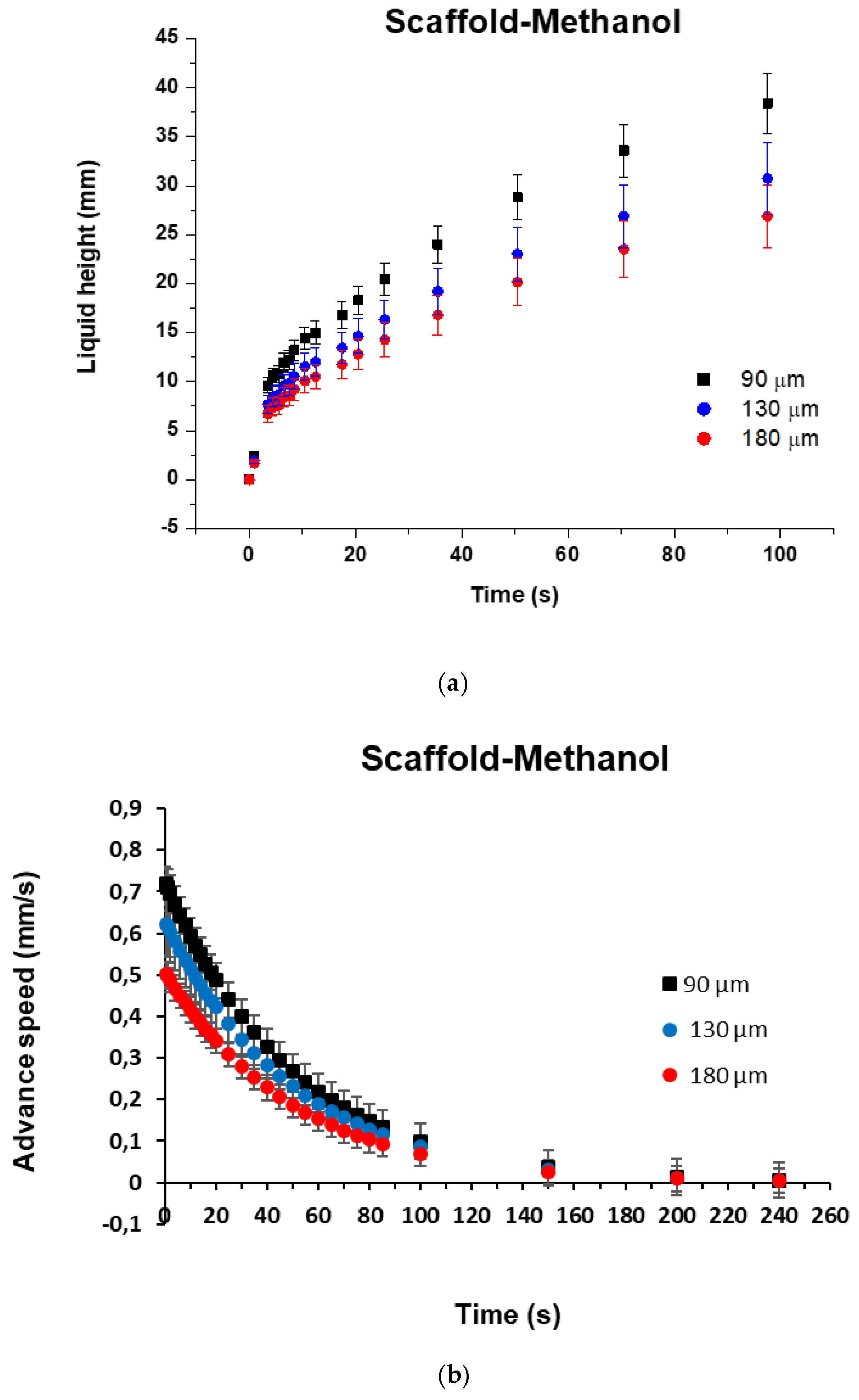
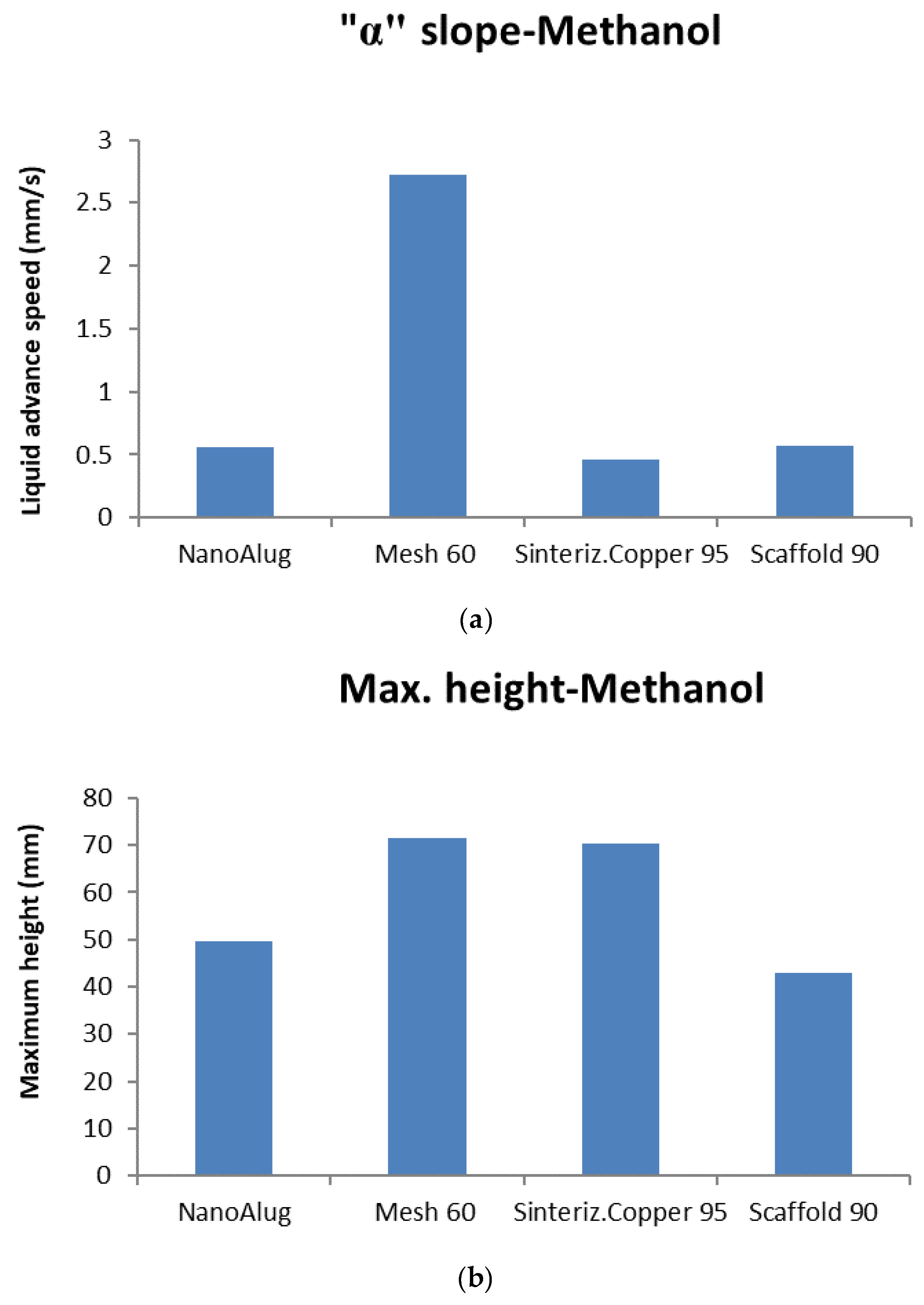
The first test was performed to measure the liquid pumping capacity and capillary action of wicks created by different techniques (sintering, mesh, SLM). The wick specifications were a speed of advance of 0.031 mm/s at a height of 30 mm imposed by a particular 80 W LHP application. It was concluded that the faster the ascent of the fluid, the better the wick performance. With regard to capillary action, the SLM wick (scaffold) presented a 23% faster response than the sintered powder, although the stainless-steel mesh offered the fastest response.
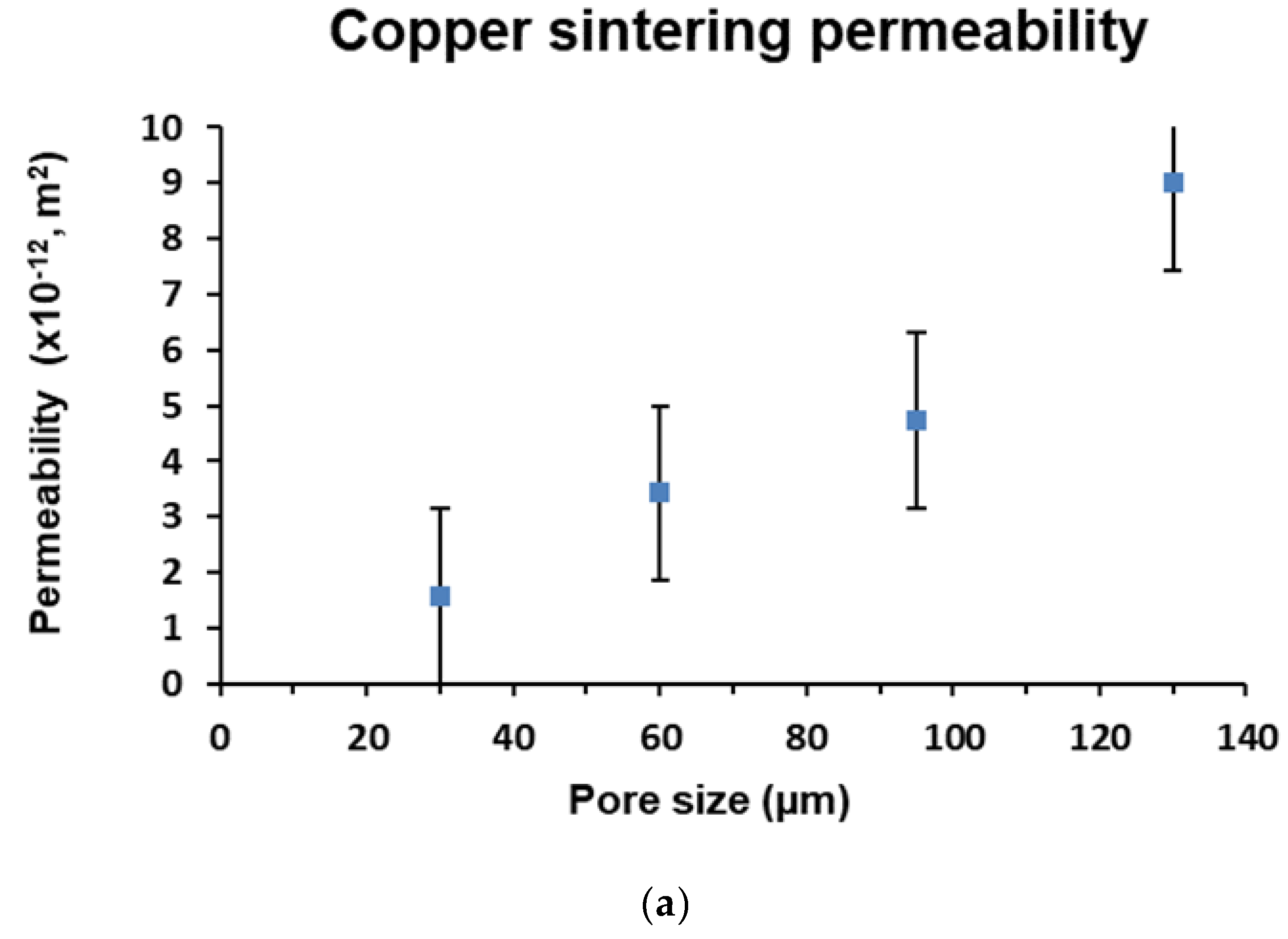
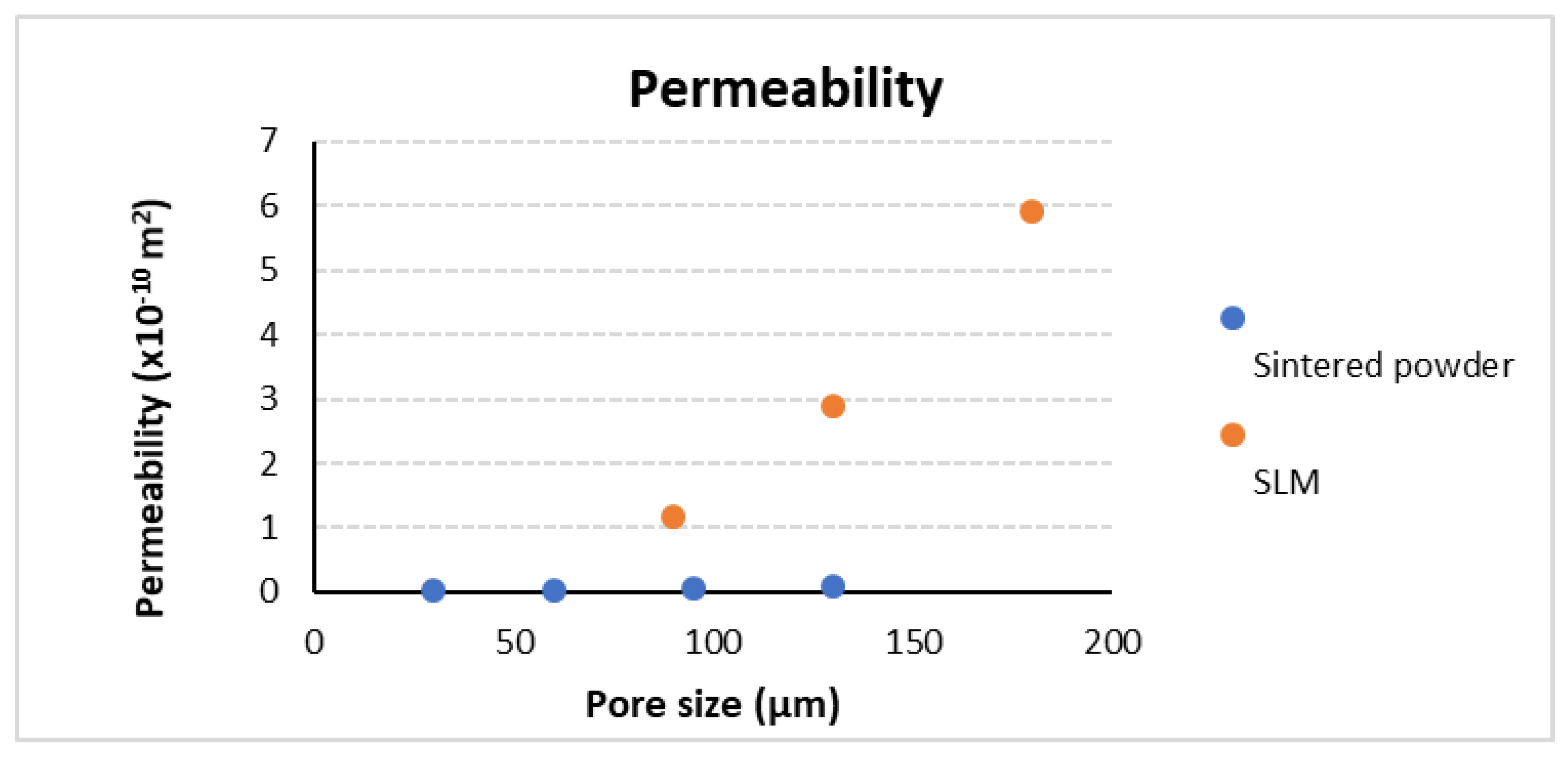
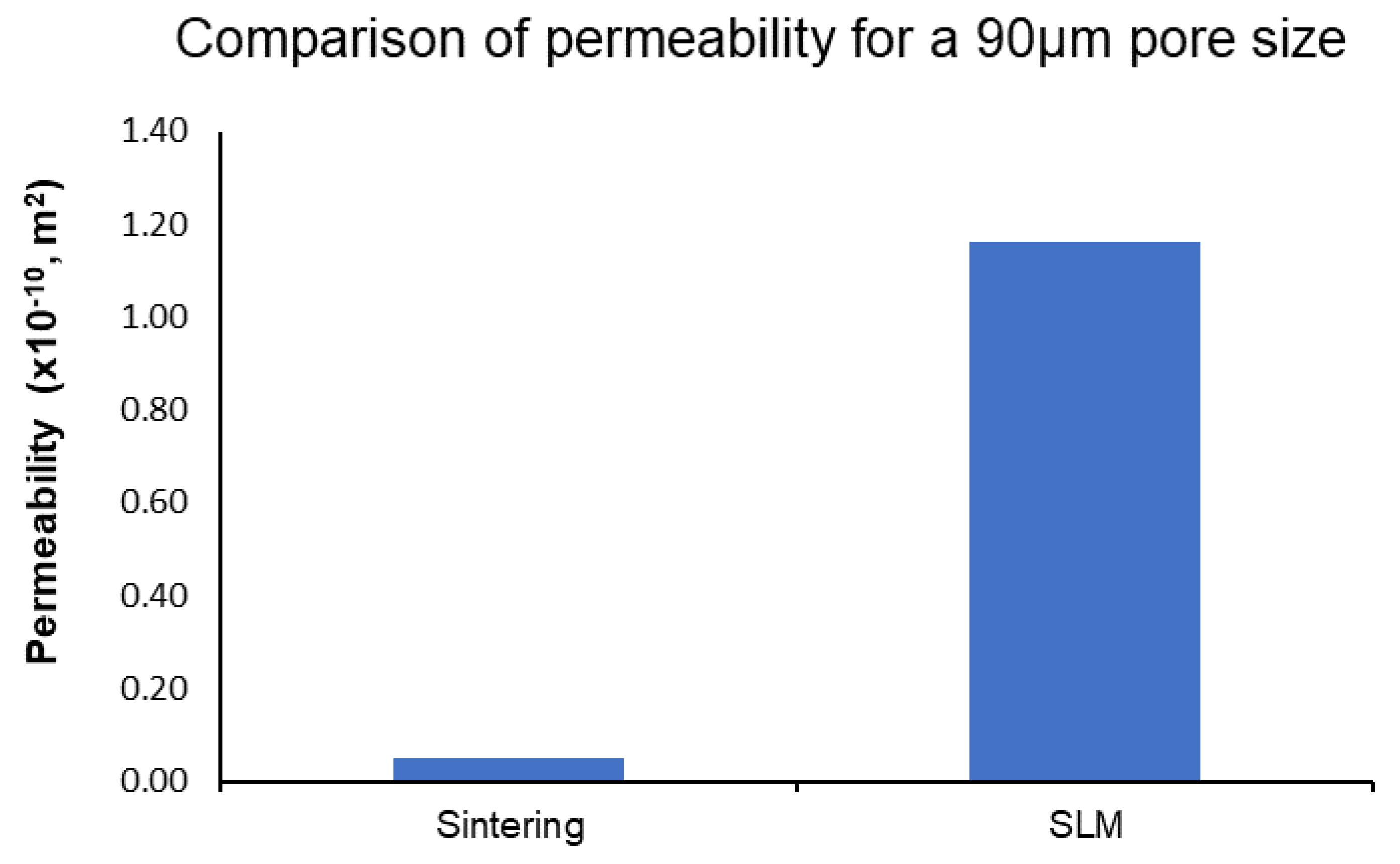
Regarding permeability, scaffold samples presented values of two orders of magnitude higher than that of the sintered powder, showing its lower resistance to fluid flow. In this study, the hydraulic behavior of the scaffold design was superior to the behavior of sintering copper, suggesting that it is more suitable for implementation in the 80 W LHP application.
Finally, it has been concluded that SLM technology can easily and precisely create the wick structure that best fits the heat pipe requirements in terms of fluid pumping, capillary action, and permeability.

Author Contributions

J.E. and J.M.B. conceived and designed the whole experimental procedure and assisted with planning trials and the interpretation of results. A.B. and R.S. provided constructive instructions in the methodology used for the preparation and post-processing of this study, supervised the manuscript, and were responsible for funding acquisition.

Funding

This research received no external funding.

Acknowledgments

The authors are very grateful to the Navarre Government for its continuous support of the research and development program at NAITEC, and to the Basque Government for support through projects IT781-13 and IT1314-19, respectively.

Conflicts of Interest

The authors declare no conflict of interest.

Nomenclature

A1, A2Constants of the fluid for Equations (3) and (4) and Table 3, Table 4 and Table 5, respectively
AMAdditive manufacturing
CADComputer aided design
dDiameter (mm)
DAverage pore size (μm)
EDSEnergy dispersive spectroscopy
HMaximum height of capillary (m)
hfvVaporization latent heat (kJ/kg)
IRInfra Red
LPermeability length (mm)
LHPLoop heat pipe
PCPersonal Computer
PMPorous media
m ˙ C Liquid evaporation rate at the liquid-vapor interface (kg/s)
m ˙ Wick capillary pumping capacity or liquid velocity through the wick (kg/s)
ΔPPressure drop
Q ˙ Heat transport capacity (W)
ReReynolds number (dimensionless)
SPowder size (μm)
SEISecondary electron imaging
SEMScanning electron microscope
SILGSilica gel
SISStream imaging system
SLMSelective laser melting
TTemperature (°C)
tTime (s)
t1, t2Constants of the wick for Equations (3) and (4) and Table 3, Table 4 and Table 5 respectively
WPitch (mm)
yLiquid height (mm)
Symbols
αAdvance speed of liquid front (mm/s)
ρDensity (kg/m3)
μDynamic viscosity (kg s/m2).
σlvFluid’s surface tension coefficient (N/m)
τTortuosity
κPorous media permeability (m2)
εWick porosity (0/1)
φContact angle
reffCapillary radius

References

  1. Chen, X.; Ye, H.; Fan, X.; Ren, T.; Zhang, G. A review of small heat pipes for electronics. Appl. Therm. Eng. 2016, 96, 1–17. [Google Scholar] [CrossRef] [Green Version]
  2. Kumar, P.; Wangaskar, B.; Khandekar, S.; Balani, K. Thermal-fluidic transport characteristics of bi-porous wicks for potential loop heat pipe systems. Exp. Therm. Fluid Sci. 2018, 94, 355–367. [Google Scholar] [CrossRef]
  3. Ji, X.; Li, H.; Xu, J.; Huang, Y. Integrated flat heat pipe with a porous network wick for high-heat-flux electronic devices. Exp. Therm. Fluid Sci. 2017, 85, 119–131. [Google Scholar] [CrossRef]
  4. Li, H.; Wang, X.; Liu, Z.; Tang, Y.; Li, Y. Experimental investigation on the sintered wick of the anti-gravity loop-shaped heat pipe. Exp. Therm. Fluid Sci. 2015, 68, 689–696. [Google Scholar] [CrossRef]
  5. Weng, C.Y.; Leu, T.S. Two-phase flow pattern based theoretical study of loop heat pipes. Appl. Therm. Eng. 2016, 98, 228–237. [Google Scholar] [CrossRef]
  6. Jafari, D.; Shamsi, H.; Filippeschi, S.; di Marco, P.; Franco, A. An experimental investigation and optimization of screen mesh heat pipes for low-mid temperature applications. Exp. Therm. Fluid Sci. 2017, 84, 120–133. [Google Scholar] [CrossRef]
  7. Boubaker, R.; Platel, V. Vapor pocket behavior inside the porous wick of a capillary pumped loop for terrestrial application. Appl. Therm. Eng. 2015, 84, 420–428. [Google Scholar] [CrossRef]
  8. Dezhi, W.; Xiaoving, W. Influence of packing density of porous media for LHP. Powder Technol. 2014, 258, 6–10. [Google Scholar]
  9. Yu, P.L.; Yin, F.X.; Wu, Z.F. Effect of apparent density of powder and shape of the particle on preparation and properties of sintered stainless steel porous material. Powder Metall. 2012, 30, 177–181. [Google Scholar]
  10. Kleijnen, R.G.; Schmid, M.; Wegener, K. Production and Processing of a Spherical Polybutylene Terephthalate Powder for Laser Sintering. Appl. Sci. 2019, 9, 1308. [Google Scholar] [CrossRef]
  11. Esarte, J.; Blanco, J.M.; Bernardini, A.; San-José, J.T. Optimizing the design of a two-phase cooling system loop heat pipe: Wick manufacturing with the 3D selective laser melting printing technique and prototype testing. Appl. Therm. Eng. 2017, 111, 407–419. [Google Scholar] [CrossRef]
  12. Richard, B.; Pellicone, D.; Anderson, W.G. Loop heat pipe wick fabrication via additive manufacturing “DMLS”. In Proceedings of the 47th International Conference on Environmental Systems, Charleston, SC, USA, 16–20 July 2017. [Google Scholar]
  13. Dai, N.; Xu, X.; Li, S.; Zhang, Z. Simulation of Hybrid Photovoltaic Solar Assisted Loop Heat Pipe/Heat Pump System. Appl. Sci. 2017, 7, 197. [Google Scholar] [CrossRef]
  14. Ling, W.; Zhou, W.; Liu, R.; Qiu, Q.; Ke, Y. Operational characteristics of loop heat pipes with porous copper fiber sintered sheet as wick. Appl. Therm. Eng. 2017, 122, 398–408. [Google Scholar] [CrossRef]
  15. Kiseev, V.M.; Vlassov, V.V.; Muraoka, I. Experimental optimization of capillary structures for loop heat pipes and heat switches. Appl. Therm. Eng. 2010, 30, 1312–1319. [Google Scholar] [CrossRef]
  16. Ji, X.; Xu, J.; Li, H.; Huang, G. Switchable heat transfer mechanisms of nucleation and convection by wettability match of evaporator and condenser for heat pipes: Nano-structured surface effect. Nano Energy 2017, 38, 313–325. [Google Scholar] [CrossRef]
  17. Rabbani, A.; Jamshidi, S. Specific surface and porosity relationship for sandstones for prediction of permeability. Int. J. Rock Mech. Min. 2014, 71, 25–32. [Google Scholar] [CrossRef]
  18. Byon, C.; Kim, S.J. Capillary performance of bi-porous sintered metal wicks. Int. J. Heat Mass Transf. 2012, 55, 4096–4103. [Google Scholar] [CrossRef]
  19. Zhong, W.; Ji, X.; Li, C.; Fang, J.; Liu, F. Determination of Permeability and Inertial Coefficients of Sintered Metal Porous Media Using an Isothermal Chamber. Appl. Sci. 2018, 8, 1670. [Google Scholar] [CrossRef]
  20. Peijun, G. Dependency of tortuosity and permeability of porous media on directional distribution of pore voids. Transp. Porous Med. 2012, 95, 285–303. [Google Scholar]
  21. Li, J.; Zou, Y.; Cheng, L. Experimental study on capillary pumping performance of porous wicks for loop heat pipe. Exp. Therm. Fluid Sci. 2010, 34, 1403–1408. [Google Scholar] [CrossRef]
  22. Esarte, J.; Bernardini, A.; Blanco, J.M.; Sancibrián, R. Optimizing the design for a two-phase cooling system Loop Heat Pipe; Part A: Numerical model, characterization and validation procedure applied to a case study. Appl. Therm. Eng. 2016, 99, 892–904. [Google Scholar] [CrossRef]
  23. Fredrik, C. Permeability description by characteristic length, tortuosity, constriction and porosity. Transp. Porous Med. 2014, 103, 381–400. [Google Scholar]
  24. Berg, C. Re-examining Archie’s law: Conductance description by tortuosity and constriction. Phys. Rev. E 2012, 86, 310–314. [Google Scholar] [CrossRef]
  25. Kruth, J.P.; Froyen, L.; van Vaerenbergh, J.; Mercelis, P.; Romboutsb, M.; Lauwers, B. Selective laser melting of iron-based powder. J. Mater. Process. Tech. 2004, 149, 616–622. [Google Scholar] [CrossRef]
  26. Liu, Y.J.; Li, S.J.; Wang, H.L.; Hou, W.T.; Zhang, L.C. Microstructure, defects and mechanical behavior of beta-type titanium porous structures manufactured by electron beam melting and selective laser melting. Acta Mater. 2016, 113, 56–67. [Google Scholar] [CrossRef] [Green Version]
  27. Liu, Y.J.; Wang, H.L.; Li, S.J.; Wang, S.G.; Zhang, L.C. Compressive and fatigue behavior of beta-type titanium porous structures fabricated by electron beam melting. Acta Mater. 2017, 126, 58–66. [Google Scholar] [CrossRef]
  28. Liu, Y.J.; Li, S.J.; Zhang, L.C.; Hao, Y.L.; Sercombe, T.B. Early plastic deformation behavior and energy absorption in porous β-type biomedical titanium produced by selective laser melting. Scr. Mater. 2018, 153, 99–103. [Google Scholar] [CrossRef]
  29. Kirsch, K.L.; Thole, K.A. Pressure loss and heat transfer performance for additively and conventionally manufactures pin fin arrays. Int. J. Heat Mass Transf. 2017, 108, 2502–2513. [Google Scholar] [CrossRef]
  30. Daxiang, D.; Yong, T.; Guanghan, H.; Longsheng, L.; Dong, Y. Characterization of capillary performance of composite wicks for two-phase heat transfer devices. Int. J. Heat Mass Transf. 2013, 56, 283–293. [Google Scholar]
  31. Tang, Y.; Hu, Z.; Qing, J.; Xie, Z.; Fu, T.; Chen, W. Experimental investigation on isothermal performance of the micro-grooved heat pipe. Exp. Therm. Fluid Sci. 2013, 47, 143–149. [Google Scholar] [CrossRef]
  32. Khabbazi, A.E.; Ellis, J.S.; Bazylak, A. Developing a new form of the Kozeny–Carman parameter for structured porous media through lattice-Boltzmann modeling. Comput. Fluids 2013, 75, 35–41. [Google Scholar] [CrossRef]
  33. Tien, C.; Ramarao, B.V. Can filter cake porosity be estimated based on the Kozeny–Carman equation? Powder Technol. 2013, 237, 233–240. [Google Scholar] [CrossRef]
  34. Valdes-Parada, F.J.; Ochoa-Tapia, J.A.; Alvarez-Ramirez, J. Validity of the permeability Carman_Kozeny equation: A volume averaging approach. Phys. A 2009, 388, 789–798. [Google Scholar] [CrossRef]
  35. Otaru, A.J.; Morvan, H.P.; Kennedy, A.R. Measurement and simulation of pressure drop across replicated porous aluminium in the Darcy-Forchheimer regime. Acta Mater. 2018, 149, 265–273. [Google Scholar] [CrossRef]
  36. Chen, Z.; Zong, X.; Shi, J.; Zhang, X. Online Monitoring Based on Temperature Field Features and Prediction Model for Selective Laser Sintering Process. Appl. Sci. 2018, 8, 2383. [Google Scholar] [CrossRef]
  37. Ronca, A.; Rollo, G.; Cerruti, P.; Fei, G.; Gan, X.; Buonocore, G.G.; Lavorgna, M.; Xia, H.; Silvestre, C.; Ambrosio, L. Selective Laser Sintering Fabricated Thermoplastic Polyurethane/Graphene Cellular Structures with Tailorable Properties and High Strain Sensitivity. Appl. Sci. 2019, 9, 864. [Google Scholar] [CrossRef]
  38. Hwang, T.W.; Woo, Y.Y.; Han, S.W.; Moon, Y.H. Fabrication of Mesh Patterns Using a Selective Laser-Melting Process. Appl. Sci. 2019, 9, 1922. [Google Scholar] [CrossRef]
  39. Vazquez, L.; Blanco, J.M.; Ramis, R.; Peña, F.; Diaz, D. Robust methodology for steady state measurements estimation-based framework for a reliable long term thermal power plant operation performance monitoring. Energy 2015, 93, 923–944. [Google Scholar] [CrossRef]
  40. Dukhan, N.; Bagcı, O.; Ozdemir, M. Metal foam hydrodynamics: Flow regimes from pre-Darcy to turbulent. Int. J. Heat Mass Transf. 2014, 77, 114–123. [Google Scholar] [CrossRef]
  41. Tang, H.; Tang, Y.; Yuan, W.; Peng, R.; Lu, L.; Wan, Z. Fabrication and capillary characterization of axially micro-grooved wicks for aluminum flat-plate heat pipes. Appl. Therm. Eng. 2018, 129, 907–915. [Google Scholar] [CrossRef]
  42. Famouri, M.; Carbajal, G.; Li, C. Transient analysis of heat transfer and fluid flow in a polymer-based micro flat heat pipe with hybrid wicks. Int. J. Heat Mass Transf. 2014, 70, 545–555. [Google Scholar] [CrossRef]
  43. Ling, W.; Zhou, W.; Yu, W.; Chu, X. Capillary pumping performance of porous copper fibber sintered wicks for loop heat pipes. Appl. Therm. Eng. 2018, 129, 1582–1594. [Google Scholar] [CrossRef]
Figure 1. Image of stainless-steel structures manufactured by selective laser melting (SLM).
Applsci 09 02905 g001
Figure 2. Capillary pumping measurement equipment; (a) scheme of the test bench and (b) detail of the sample.
Applsci 09 02905 g002
Figure 3. Pumping curve for stainless-steel mesh of pitch 60 µm in methanol.
Applsci 09 02905 g003
Figure 4. Permeability test bench (left) and simplified scheme (right).
Applsci 09 02905 g004
Figure 5. Differences between the two types of silica gel with methanol as a working fluid; (a) liquid height and (b) advance speed.
Applsci 09 02905 g005
Figure 6. Metallic meshes of the different aperture widths analyzed; (a) 60 μm, (b) 200 μm, and (c) 300 μm.
Applsci 09 02905 g006aApplsci 09 02905 g006b
Figure 7. Capillary pumping curve for stainless-steel mesh for the three different pitches; (a) liquid height and (b) advance speed.
Applsci 09 02905 g007aApplsci 09 02905 g007b
Figure 8. Pumping or capillary action curve for sintered copper powder samples of different pore size; (a) liquid height and (b) advance speed.
Applsci 09 02905 g008
Figure 9. Final result of the 3D printed wick.
Applsci 09 02905 g009
Figure 10. Samples of scaffold internal structure; (a) fine capillary of 90 μm and (b) thick capillary of 180 μm.
Applsci 09 02905 g010
Figure 11. Pumping curve for scaffold of stainless-steel in methanol for the two capillary configurations; (a) liquid height and (b) advance speed.
Applsci 09 02905 g011
Figure 12. Darcy’s law for a 95 μm copper sintering sample in methanol.
Applsci 09 02905 g012
Figure 13. Comparative test; (a) permeability vs. pore size of copper powder sintering, and (b) permeability vs. meniscus size of scaffold-SLM.
Applsci 09 02905 g013aApplsci 09 02905 g013b
Figure 14. Comparative test for different techniques with a similar pore size; (a) liquid advance speed and (b) maximum height of pumping.
Applsci 09 02905 g014
Figure 15. Comparative of permeability.
Applsci 09 02905 g015
Figure 16. Comparative test on permeabilities between sintering and scaffold for a similar pore size of 90 μm.
Applsci 09 02905 g016
Table 1. Main features of the PENTAX Optio Z10 camera (RICOH, Tokyo, Japan).
ModelPENTAX Optio Z10
Resolution8.0 Megapixels
Optical Zoom
Size3264 × 2448
Table 2. Technical features of JEOL (JSM5900LV) scanning electron microscope (SEM).
Resolution3 nm @ 30 kV (SEI: Secondary electron imaging)
Sample8” max., 125 mm X, 100 mm Y
Beam Current0.5–1 nA
Accelerating Voltage20 kV
Working Distance10–12 mm
Imaging12–20 arrows
Table 3. Properties of silica gel sheets and capillary action (methanol).
MaterialS (μm)A (mm/s)A1 (mm)t1 (s)A2 (mm)t2 (s)
Silica Gel sheetsAlugram-SIL G5–170.1418.22767457.868830.4723626.70651
Nano Alugram-SIL G2–100.1623.52259210.024625.9888716.58615
Table 4. Metallic mesh characteristics and capillary action (methanol).
Mesh (μm)d (mm)W (mm)εα (mm/s)A1t1A2t2
600.024–0.0270.060.47562.3831.7913518.8775143.2307518.87751
2000.072–0.0780.15–0.160.45191.1753.4434524.760815.396772.81373
3000.170.30.40740.8844.9021721.229733.81120.00626
Table 5. Characteristics of sintered powder copper samples and capillary action (methanol).
D (μm)εA (mm/s)A1t1A2t2
300.5730.6106.1836149.38215.5330.00626
600.5730.5496.93418149.3914.180.00626
950.5730.2761.30656149.398.968290.00626
1300.5730.252.43766149.397.670.00626
Table 6. Technological parameters using the selective laser melting (SLM) printer.
FeatureValue
Laser power200 W
Exposure time286 µs
Layer thickness50 µm
Scan speed350 mm/s
3D optics configurationDual 1 × 700 W
Table 7. Characteristics of scaffold samples and capillary action (methanol).
D (μm)εA (mm/s)A1t1A2t2
900.300.250036.404250.2136.42530.00626
1800.450.001325.482550.214.49760.00626

